Projects with the TTGO T-Display
Installation and power measurements are found at the bottom of this document.
MicroPython
Some example programs:
- Mandelbrot
- green terminal
- prime numbers
With the TFT display in /tft folder
- Mandelbrot
- Scrolling
- Matrix
Arduino C
Examples here are:
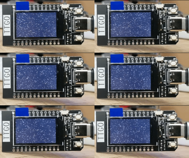
Installation of Arduino
You need the following 5 steps to be able to program your T-Display with your Laptop/PC.
Installation of MicroPython
Simplified Installation
You need 2 programs and 1 file to get started with MicroPython on the T-Display. I downloaded the most recent in November 2020 and put them in the first v0.1 release. They include:
- esptool 2.6.1 to install the firmware
- firmware.bin micropython v1.12 with ST7789V driver library
- Thonny 3.3.0 for Windos, other operation systems
Connect your T-Display to a USB port of your computer and determine the port. You can do this by right-click on the Windows symbol > Device Manager > ports (COM & LPT) and there you’ll find Silicon Labs CP210x USB to UART Bridge (COM6). Here COM6 would be your serial port. Open cmd or powershell and navigate to the folder with the esptool.exe and firmware.bin.
- Check your board with
esptool.exe --port COM6 flash_id - Erase the flash
esptool --port COM6 erase_flash - Flash the new firmware with
esptool --chip esp32 --port COM6 --baud 460800 write_flash -z 0x1000 firmware.bin
MicroPython should now be running on your T-Display. To see this we need to upload a program. Install Thonny. After opening Thonny change the settings to Tools > Options… > Interpreter. Here you select MicroPython (ESP32) and the correct Port or WebREPL Silicon Labs CP210x USB to UART Bridge (COM6). You might have to press STOP once and then will be greeted with
  MicroPython v1.12-464-gcae77daf0-dirty on 2020-06-28; ESP32 module with ESP32
  Type "help()" for more information.
>>>
Here you can directly try your first hello_world.
>>> print("Hello world!")
Hello world.
Original sources with updates
First he have to obtain the two programs and the firmware.
esptool.py
The esptool.py is the software provided by esp to upload the firmware to their SoCs. I got mine from the Arduino installation at the path C:\Users\You\AppData\Local\Arduino15\packages\esp32\tools\esptool_py\2.6.1\. You can download the latest version from github:
https://github.com/espressif/esptool
firmware
The latest MicroPython firmware for the ESP32 can be found on micropython.org. This firmware does not include a driver for the ST7789 display. You have several options to include the display library.
IDE - integrated development environment
To edit, upload and download your python programs to your ESP32 you need a program on your laptop. Some options include:
If you have already Arduino IDE you can directly connect to the REPL interface:
>>> print("Hello world!")
Hello world.
Hardware
Many pins of the ESP32 that are related to the ADC converter are exposed on the T-Display. This makes this board suitable for a variety of measurement applications. The pins are:
| PIN | ADC | T-Display | L/R |
|---|---|---|---|
| 36 | ADC1_CH0 | R | |
| 37 | ADC1_CH1 | R | |
| 38 | ADC1_CH2 | R | |
| 39 | ADC1_CH3 | R | |
| 32 | ADC1_CH4 | R | |
| 33 | ADC1_CH5 | R | |
| 34 | ADC1_CH6 | battery/2 | |
| 35 | ADC1_CH7 | button | |
| 4 | ADC2_CH0 | backlight on/off | |
| 0 | ADC2_CH1 | button | |
| 2 | ADC2_CH2 | L | |
| 15 | ADC2_CH3 | L | |
| 13 | ADC2_CH4 | L | |
| 12 | ADC2_CH5 | L | |
| 14 | ADC2_CH6 | ||
| 27 | ADC2_CH7 | R | |
| 25 | ADC2_CH8 | R | |
| 26 | ADC2_CH9 | R | |
| 21 | SDA | ||
| 22 | SCL |
Power consumption
- Running 66 mA
- WiFi 80-140 mA
- CPU 80 MHz 48 mA
- Light Sleep 9 mA
Power consumption
As measured in April 2020 the board needs 68 mA for running. With a battery of 1000 mAh you can use it for 9 hours.
Further measurement has been conducted in November 2020. The results.
- Running 66 mA
- WiFi 80-140 mA
- CPU 80 MHz 48 mA
- Light Sleep 9 mA
You can directly measure the voltage of the LiPo battery on Pin 34. This can be seen in the provided schematics from TTGO for the T-Display:


The pin on the T-Display is 34 (channel ADC1_CH6) with a 1:2 battery voltage divider.
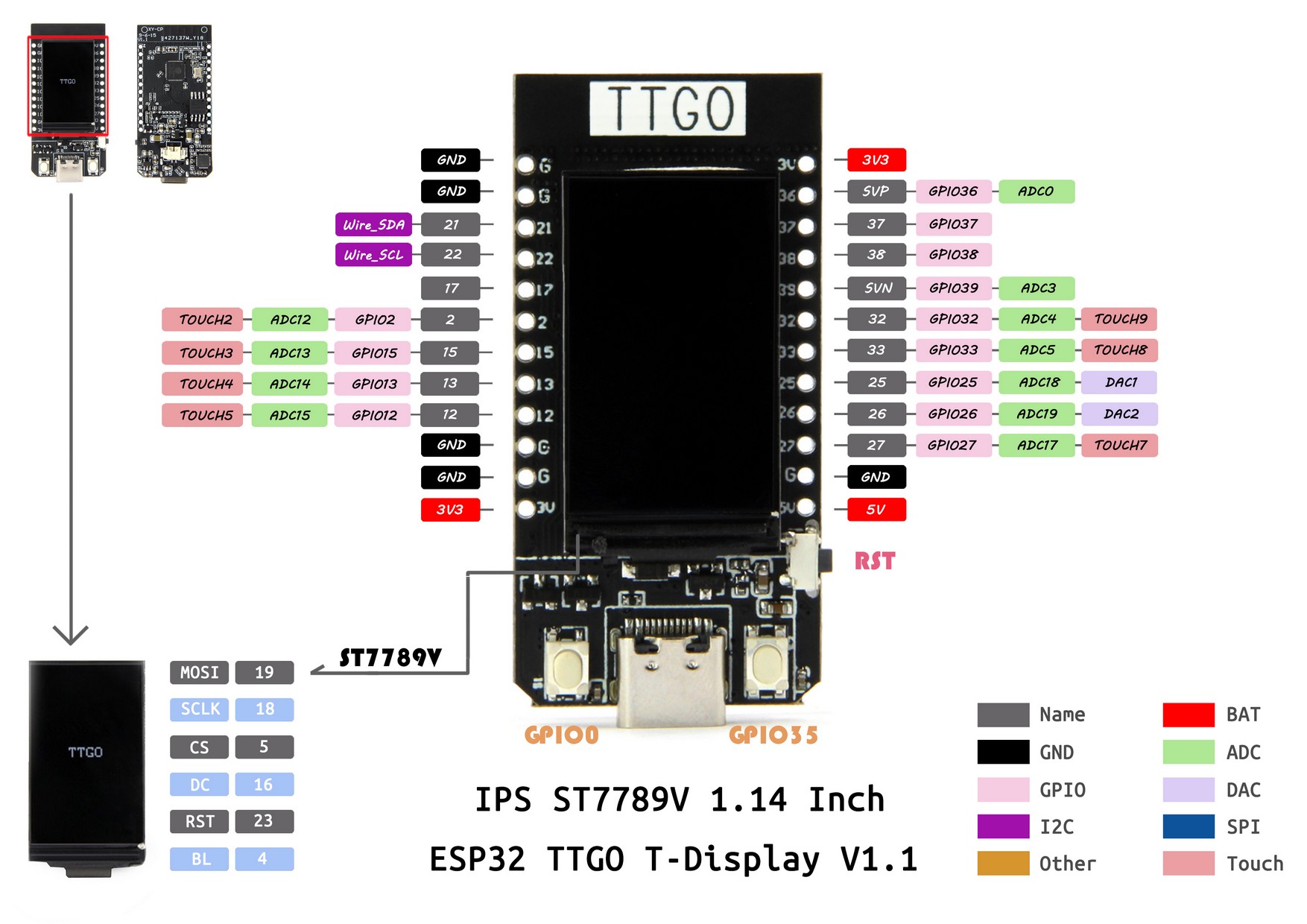
I2C connector
2020/07/09
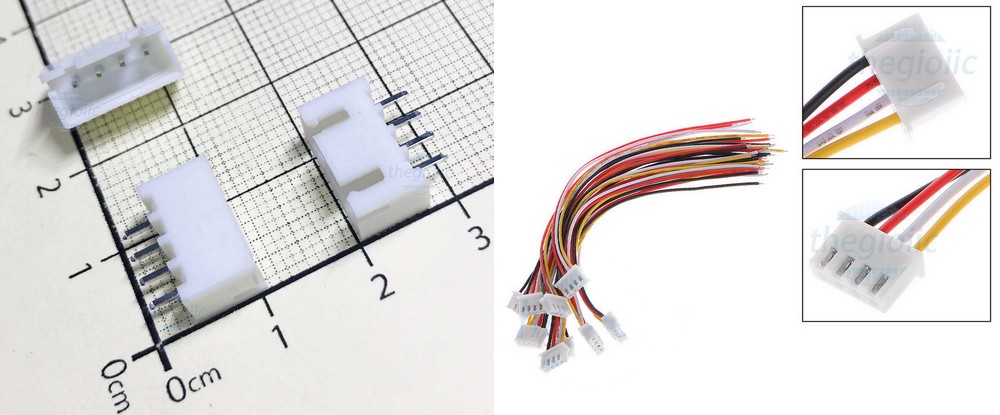
Following the inspiration of SparkFun with their QWIIC connector I tried to replicate the pin order. But instead of SMD 1.0 mm connector I just use the regular 2.54mm raster with XH connector on the board and respective 4 pin connector wire.
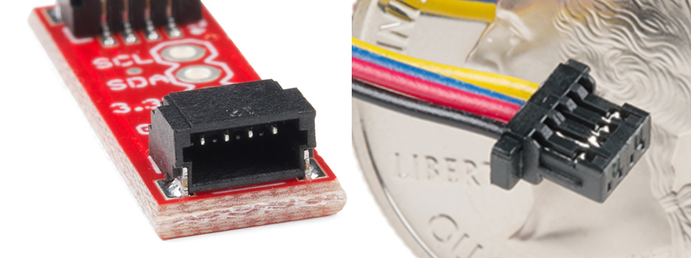
Following the same order the pins are assigned:
- black - GND
- red - 3.3 V
- blue - SDA
- yellow - SCL
The order does not match several OLED displays, but the ZS-042 rtc clock, the 1602 display adapter and many more.
2020/11/27
With the new T-Display project I included the I2C connector as well. The pins look like this:
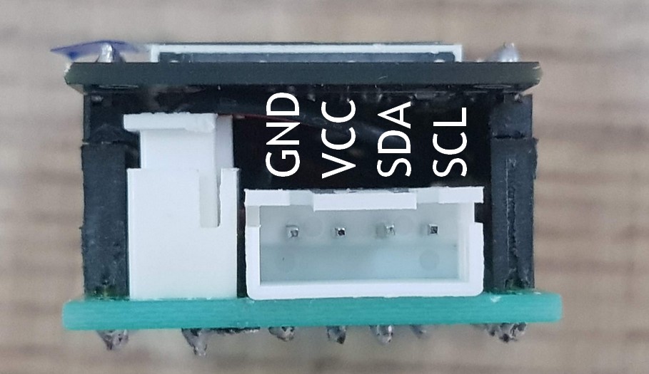
At the ESP32 SCL (SCK) is on GPIO 22 and SDA (SDI) is on GPIO 21.

