Solarmeter
This project continuously measures the output power of a solar cell and a wind generator on the roof of building A. The data is collected in Ho Chi Minh City 2020 and part of an EE (extended essay) in IB Physics at the AISVN. More pictures and descriptions here:
https://sites.google.com/ais.edu.vn/solar
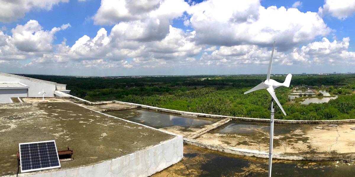
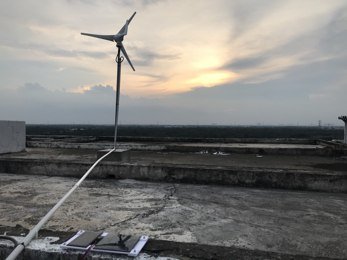
This is how our outdoor setup with one 500W wind generator and a 60W solar panel looks like. Two smaller panels for ESP32 power and hybrid generator are not shown.
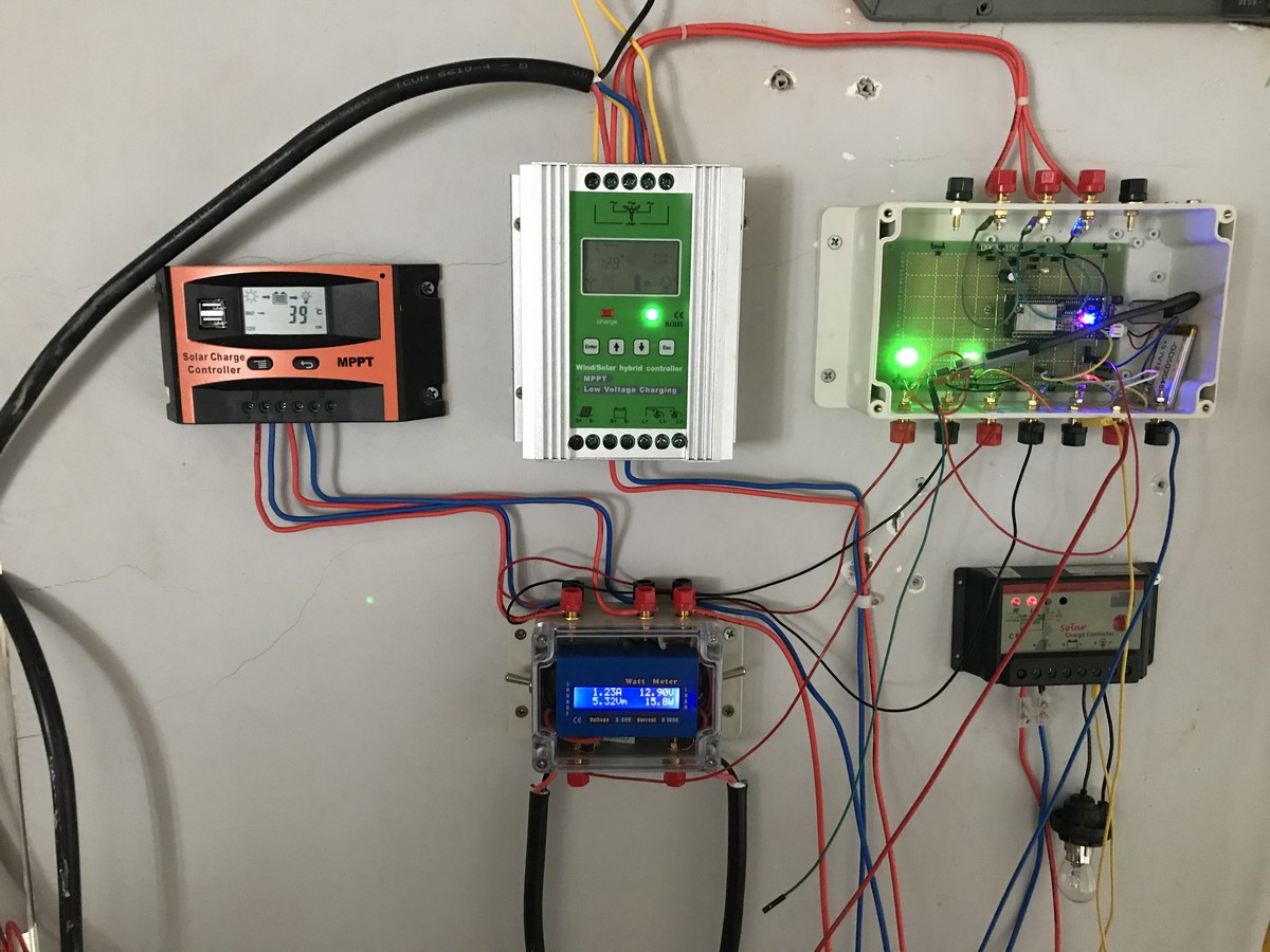
The electronics part in the room below looks like this:
And this is a sample data collection from one of the first days:
Setup
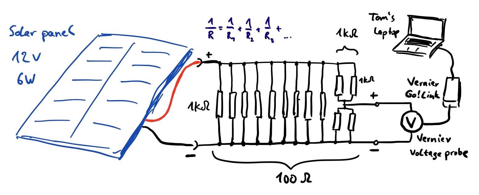
The initial setup from December 2019 requires a Laptop with Vernier software to measure just one data point. The circuit looks like this:
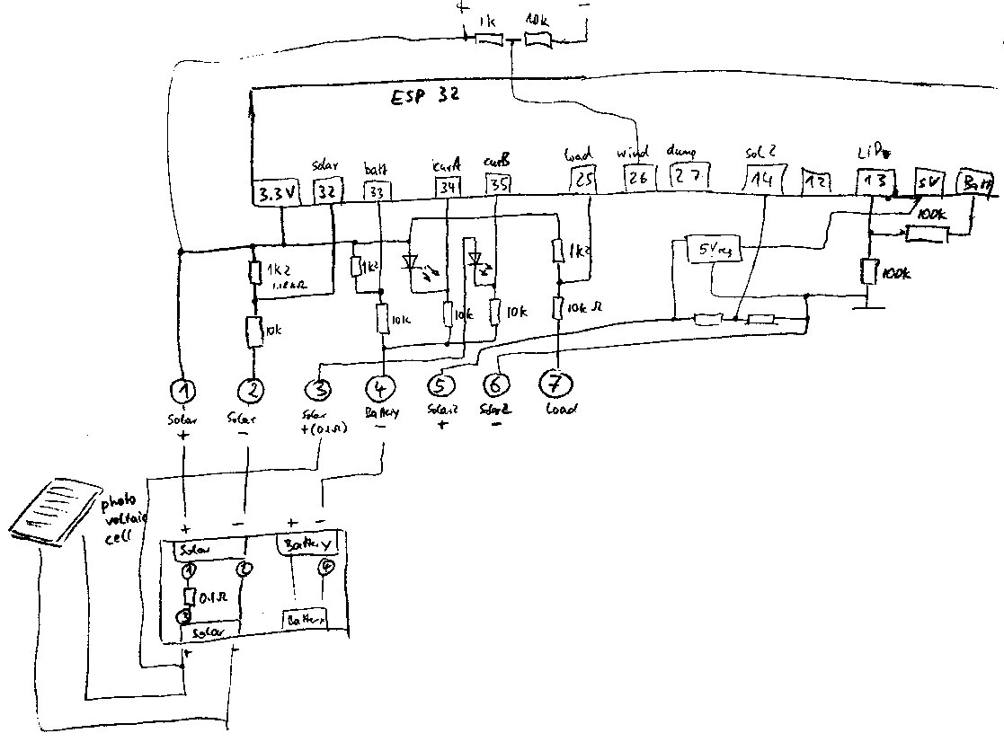
This is the circuit diagram from June 5th, 2020 (last day of school):
Materials

We take an ESP32 for measuring and transmitting the data over Wifi.
Power will be provided from the solar cell, and have a backup LiPo battery with a JST-PH 2.0 connector.
I ordered some setup materials:
- Solar panel 12V 3W 145x145mm enough for ESP32?
- Solar panel 12V 1.5W 115x85mm I guess that’s what Tom uses
- Solar panel 5V .25W 45x45mm small and cheap - sufficient? Without step down converter?
- Step down to 5V
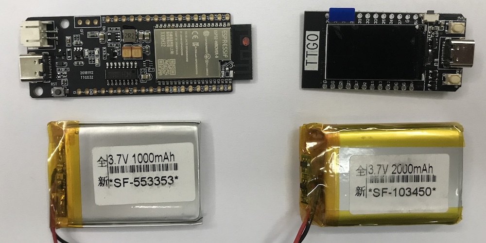
- ESP32 with display, USB-C 222000 VND - $ 9.40 with 1.14” display
- TTGO T-Koala with USB-C and battery JST 2.0 interface, red power LED, green to control and blue LiPo charge
- Battery 1000 mAh for backup during the night
Software
// Solar- and windmeter at AISVN v0.10
// 2020/06/17
//
// pin:       32,      33,       34,       35,   14,   26,   27,     12,   13
// value:  solar, battery, currentA, currentB, load, wind, temp, solar2, LiPo
//
// submit: solar, battery, current, power, load, wind, temp, solar2, LiPo, bootCount
//             0,       1,       2,     3,    4,    5,    6,      7,    8,

#include <WiFi.h>
#include <Wire.h>
#include <credentials.h>  // WiFi credentials in separate file
#include <soc/sens_reg.h>

RTC_DATA_ATTR int bootCount = 0;
static RTC_NOINIT_ATTR int reg_b; // place in RTC slow memory so available after deepsleep

// Replace with your SSID and Password + uncomment
// const char* ssid     = "REPLACE_WITH_YOUR_SSID";
// const char* password = "REPLACE_WITH_YOUR_PASSWORD";

// Replace with your unique IFTTT URL resource + uncomment
// const char* resource = "/trigger/data/with/key/value";

// Maker Webhooks IFTTT
const char* server = "maker.ifttt.com";

// Time to sleep
uint64_t uS_TO_S_FACTOR = 1000000;  // Conversion factor for micro seconds to seconds
// sleep for 2 minutes = 120 seconds
uint64_t TIME_TO_SLEEP = 120;

//    32,      33,       34,       35,   14,   26,   27,     12,   13
// solar, battery, currentA, currentB, load, wind, temp, solar2, LiPo

int voltage[9] = {0, 0, 0, 0, 0, 0, 0, 0, 0};       // all voltages in millivolt
int pins[9] = {32, 33, 34, 35, 14, 26, 27, 12, 13}; // solar, battery, curA, curB, load, wind, temp, solar2, LiPo
int ledPin = 5;

void setup() {
  pinMode(ledPin, OUTPUT);
  digitalWrite(ledPin, HIGH);
  Serial.begin(115200);
  // determine cause of reset
  esp_reset_reason_t reason = esp_reset_reason();
  Serial.print("reason ");Serial.println(reason);
  // get reg_b if reset not from deep sleep
  if ((reason != ESP_RST_DEEPSLEEP)) {
    reg_b = READ_PERI_REG(SENS_SAR_READ_CTRL2_REG);
    Serial.println("Reading reg b.....");
  }
  Serial.print("reg b: ");
  printf("%" PRIu64 "\n", reg_b);
  delay(50);
  digitalWrite(ledPin, LOW);
  bootCount++;
  delay(1000);
  measureVoltages();

  digitalWrite(ledPin, HIGH);
  initWifi();
  makeIFTTTRequest();
  digitalWrite(ledPin, LOW);

  // enable timer deep sleep
  esp_sleep_enable_timer_wakeup(TIME_TO_SLEEP * uS_TO_S_FACTOR);
  Serial.println("Going to sleep now");
  // start deep sleep for 120 seconds (2 minutes)
  esp_deep_sleep_start();
}

void loop() {
  // sleeping so wont get here
}

// Establish a Wi-Fi connection with your router
void initWifi() {
  Serial.print("Connecting to: ");
  Serial.print(ssid);
  WiFi.begin(ssid, password);

  int timeout = 10 * 4; // 10 seconds
  while(WiFi.status() != WL_CONNECTED  && (timeout-- > 0)) {
    delay(250);
    Serial.print(".");
  }
  Serial.println("");

  if(WiFi.status() != WL_CONNECTED) {
     Serial.println("Failed to connect, going back to sleep");
  }

  Serial.print("WiFi connected in: ");
  Serial.print(millis());
  Serial.print(", IP address: ");
  Serial.println(WiFi.localIP());
}

// Make an HTTP request to the IFTTT web service
void makeIFTTTRequest() {
  Serial.print("Connecting to ");
  Serial.print(server);

  WiFiClient client;
  int retries = 5;
  while(!!!client.connect(server, 80) && (retries-- > 0)) {
    Serial.print(".");
  }
  Serial.println();
  if(!!!client.connected()) {
    Serial.println("Failed to connect...");
  }

  Serial.print("Request resource: ");
  Serial.println(resource);

  String jsonObject = String("{\"value1\":\"") + voltage[0]/1000.0
                                       + "|||" + voltage[1]/1000.0
                                       + "|||" + voltage[2]/1000.0
                          + "\",\"value2\":\"" + voltage[3]/1000.0
                                       + "|||" + voltage[4]/1000.0
                                       + "|||" + voltage[5]/1000.0
                          + "\",\"value3\":\"" + voltage[6]/10.0
                                       + "|||" + voltage[7]/1000.0
                                       + "|||" + voltage[8]/1000.0
                          + "|||" + bootCount + "\"}";

  client.println(String("POST ") + resource + " HTTP/1.1");
  client.println(String("Host: ") + server);
  client.println("Connection: close\r\nContent-Type: application/json");
  client.print("Content-Length: ");
  client.println(jsonObject.length());
  client.println();
  client.println(jsonObject);

  int timeout = 5 * 10; // 5 seconds
  while(!!!client.available() && (timeout-- > 0)){
    delay(100);
  }
  if(!!!client.available()) {
    Serial.println("No response...");
  }
  while(client.available()){
    Serial.write(client.read());
  }

  Serial.println("\nclosing connection");
  client.stop();
}

void measureVoltages() {
  WRITE_PERI_REG(SENS_SAR_READ_CTRL2_REG, reg_b); // only needed after deep sleep
  SET_PERI_REG_MASK(SENS_SAR_READ_CTRL2_REG, SENS_SAR2_DATA_INV);
  Serial.print(" ** Voltages measured: ");
  for(int i = 0; i < 9; i++) {
    // multisample 100x to reduce noise - 9.5 microseconds x 100 = 1ms per voltage
    voltage[i] = 0;
    for(int multi = 0; multi < 100; multi++) {
      voltage[i] += analogRead( pins[i] );
    }
    voltage[i] = voltage[i] / 100;
    Serial.print(voltage[i]);
    Serial.print("  ");
  }
  // conversion to voltage prior to voltage divider

  // pin:       32,      33,       34,       35,   14,   26,   27,     12,   13
  // value:  solar, battery, currentA, currentB, load, wind, temp, solar2, LiPo
  //
  // submit: solar, battery, current, power, load, wind, temp, solar2, LiPo, bootCount
  //             0,       1,       2,     3,    4,    5,    6,      7,    8,

  voltage[0] = int((4096 - voltage[0]) * 7.52 - 1000);  // pin32 solar    voltage divider 10k : 1.2 k Ohm 1:1
  if(voltage[0] < 0) voltage[0] = 0;
  voltage[1] = int((4096 - voltage[1]) * 7.52 - 1000);  // pin33 battery  voltage divider 10k : 1.2 k Ohm 1:1
  voltage[2] = int((voltage[3] - voltage[2]) * 5.79);   // voltage difference pin35 - pin34 x 8.4 is corrent (x0.804)
  voltage[3] = int(voltage[2] * voltage[0] / 1000);
  voltage[4] = int((4096 - voltage[4]) * 7.52 - 1000);  // pin14 load     voltage divider 10k : 1.2 k Ohm 1:1
  if(voltage[4] < 0) voltage[4] = 0;
  voltage[5] = int((4096 - voltage[5]) * 7.52 - 1000);  // pin26 wind     voltage divider 10k : 1.2 k Ohm 1:1
  if(voltage[5] < 0) voltage[5] = 0;
  voltage[6] = int((voltage[6]) * 0.804 + 129);         // pin27 temp     not connected yet
  voltage[7] = int((voltage[7]) * 4.583 + 735);         // pin12 Solar2   voltage divider 4.7k : 1k
  if(voltage[7] < 736) voltage[7] = 0;
  voltage[8] = int((voltage[8]) * 1.608 + 258);         // pin13 LiPo     voltage divider 100kOhm 2:1
  Serial.print("Boot number: ");
  Serial.println(bootCount);
}
Measurements and results
Data account is created, will be linked soon. Mostly to be found at sites.google.com/ais.edu.vn/solar.
History
2019/12/03
Interview with Tom about his EE project about renewable energy in Vietnam. As for an EE (extended essay in the IB international baccalaureate) in physics an experiment should be included. And we can investigate the wind and solar power here in Nha Be on the roof of the 5th floor of the school building.
To collect data I created a new Google account as aisvn.data for emails and communication (MQTT, IFTTT).
2019/12/08
The website sites.google.com/ais.edu.vn/solar is created. The measured data from the last 36 hours is displayed in an interactive graph.
2019/12/14
I created a jupyter notebook with the first informations. The document can be found here. A copy is included in software.
2019/12/17
For about an hour during assigned study we tried to measure the characteristics of a 12 Volt 6 Watt solar panel that the school provided. The values are measured with the Vernier voltage probe and the current probe. Unfortunately the voltage probe has a maximum voltage range of 10 Volt, while the solar panel provides up to 16 Volt without any load.
Solution 1: A voltage divider made of two 1 kiloOhm resistor divided the output by 2 and moved it into the voltage limit of the probe. A successful reading now indicated the second problem: Without any load the output voltage is almost constant, since it mainly derives from the band gap in the semiconductor. This is well illustrated in this graph from wikipedia:

Note that only the current increases during daytime. Since the power is a product of voltage and current, the power increases as well.
Solution 2: A MPPT (Maximum Power Point Tracking) involves a lot electronics that is well beyond the scope of IB physics. We chose to use a fixed load somewhere in the middle of the power curve. By measuring the voltage we would automatically measure the current and therefore the power.
First we had to estimate the correct resistance for the load. With the parameters of 12V and 6W one can calculate a current of I=500mA from P=VI and then apply Ohm’s law as R=U/I which results in a resitance of R=12/0.5=24 Ohm. Another way is the direct way of R=U²/P=12²/6=24 Ω. Half the power would be achieved with ca. 50 Ohm and 100 Ohm creates 25% of the maximum power on the load. Since we had plenty 1 kOhm resistors we soldered 9 of them in parallel and added 2 series of two 1 kOhm resistors from the voltage divider as well. The circuid diagram looks like this:

2020/02/27
The hybrid wind solar power generator arrives - despite the corona virus outbreak in China. Declarations with customs and DHL took some time, but it’s now here. Other parts will be ordered locally. And this controller has the MPPT we mentioned in January included!
2020/03/18
I finally create a Github repository to document this project. The ESP32 were delivered some weeks ago. Now I got the LiPo batteries as well. Connector for the feather-style boards: JST PH 2pin for reference! Purcheased at ICDAYROI in Thủ Đức.
2020/03/20
The ADC of the ESP32 is not very linear. But we want to use it to measure the voltage of the solar pannel under different load situations. There might be a compensation function. The procedure and measurement was done by Fernando Koyanagi from Florianópolis in Brazil and published in instructables.

For the future design of April 2020 the voltage is measured by the ESP32 and the value transfered to a database in the internet every 5 minutes. This gives 288 data points per day. An article at randomnerdtutorials explains the setup and programming very well;
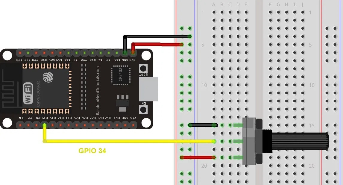
Additionally there are 4 digital switches for different loads planned. The ESP32 is activating them prior to the measurement and can combine the swithces for 16 different load values. The setup now looks like this:

With the 4 switches we can create 16 datapoints, that the ESP32 can read in 12 bit. Every 5 minutes we create therefore 24 byte of data. Over a day this accumulates to 6912 byte and in a year all data collected is 2.5 MByte.
TTGO T-Display
2020/04/01
The ordered TTGO ESP32 mainboard is pretty good! I ordered it mainly for the included LiPo charger, but it as 2 extra buttons (GPIO0 and GPIO 35) to the reset button. And a 1.14 Inch display IPS ST7789V with 135x240 pixel. And there are 13 GPIO pins left to use for 4 switches and one voltmeter under different load conditions.
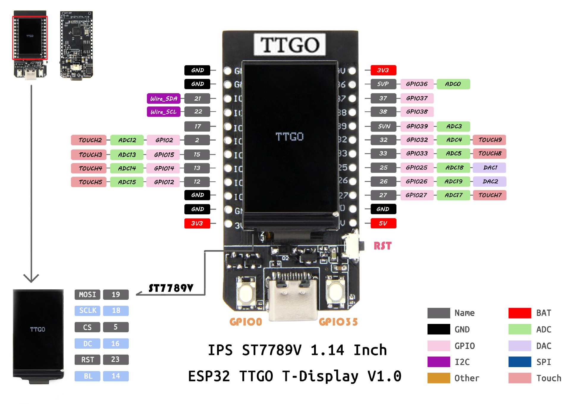
To program the display and some voltages, example code can be found at https://github.com/Xinyuan-LilyGO/TTGO-T-Display
2020/04/07
A second TTGO ESP32 arrived and is set to be programmed:
Without programming TTGO installed some software on the module. On the 135x240 display you get 22x30 characters with a 6x8 font. That’s almost as much as my first ZX81 with 32x24. You can scan for nearby 2.4GHz networks, check the power supply and go into sleep mode. The last one is of interest for our project and the power consumption with these standard settings will be tested next.
Power consumption T-Display
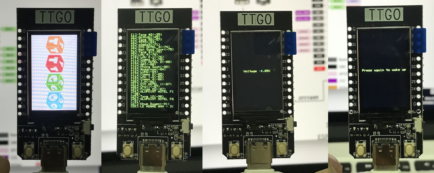
2020/04/28
With an external power supply we can check the power consumption of the TTGO. The values over USB were rather high, but it has a 3.7 LiPo battery connector and the power consumption there is significantly lower, most likely because the 5V to 3.3V step-down converter is not needed. Here are the values for 3.7 Volt over battery:
- Power on, start up and screen on: 68 mA
- WiFi scan for nearby hotspots: 108 mA
- Sleep, waiting for interrupt from key pressed: 0.35 mA
With a 1000 mAh battery and the given voltage we can calculate the power consumption and projected runtime:
- Screen on: 252 mW, runtime 14 hours 42 minutes
- WiFi on: 399 mW, runtime 9 hours 15 minutes
- Hibernate: 1.3 mW, runtime 2857 hours - or 119 days
2020/05/07
School is back open since May 4th, students are back since May 5th - and now we got the solar panel and the battery! Time to find a place on the roof in Nha Be and control software to collect and transmit data.
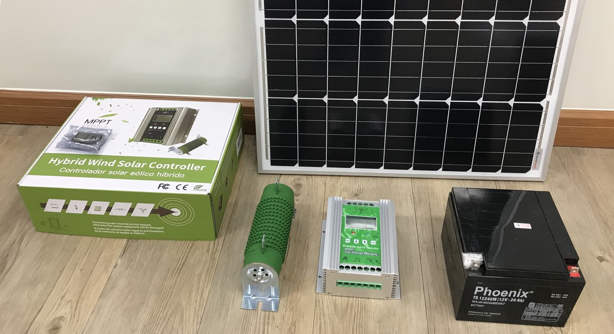
2020/05/08
The wind generator arrived just one day later! Looked at location on top of the roof, 6th floor in Nha Be. Empty room for equipment is there, rain proved, and space for the 5 wired from solar and wind to the control unit. Maybe next week start first test setup?
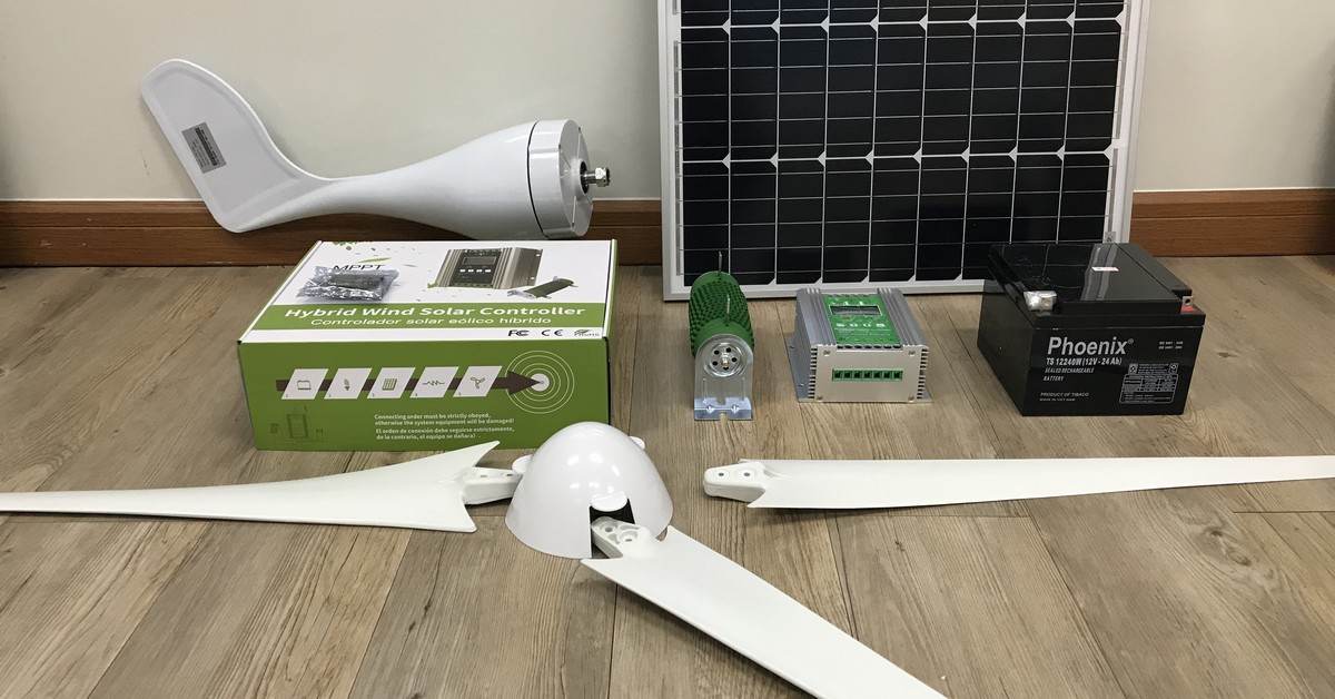
Data: JLS-500 with 24V and 500 W
2020/05/14
The TTGO can be programmed with MicroPython and devbis created both a slow python driver for the display ST7789 as well as a fast C variant. Further description of this module here. And the tft driver from Loboris is working as well, details in this instuctable from February 2020. Original data at LilyGo github.
2020/05/15
We installed the 60W solar module on the roof of our school AISVN and connected MPPT controller and 24Ah battery. Now charging over the weekend, then connect my 60W motorcycle lamp to drain the battery every night …

The stand for the 600W wind generator will be welded in the next week.
2020/05/17
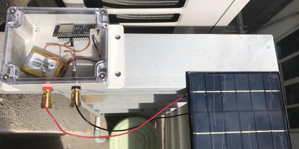
First successful setup with WEMOS LoLin32 board, 2000 mAh battery and two 1kOhm voltage divider for input on pin 34. Voltage measurement every 2 minutes, upload via IFTTT and webhooks to google sheet, then deep sleep. Setup:
Code:
// Solarmeter first attempt (all Serial.print removed), inspired by
// https://randomnerdtutorials.com/esp32-esp8266-publish-sensor-readings-to-google-sheets/

#include <WiFi.h>
#include <Wire.h>

const char* ssid     = "REPLACE_WITH_YOUR_SSID";
const char* password = "REPLACE_WITH_YOUR_PASSWORD";
const char* resource = "/trigger/value/with/key/create-one";
const char* server = "maker.ifttt.com";

uint64_t uS_TO_S_FACTOR = 1000000;  // Conversion factor for micro seconds to seconds
uint64_t TIME_TO_SLEEP = 120;
int adcValue = 0;

void setup() {
  delay(1000);
  initWifi();
  makeIFTTTRequest();
  esp_sleep_enable_timer_wakeup(TIME_TO_SLEEP * uS_TO_S_FACTOR);
  esp_deep_sleep_start(); // start deep sleep for 120 seconds (2 minutes)
}

void loop() {  // sleeping so wont get here
}

void initWifi() {  // Establish a Wi-Fi connection with your router
  WiFi.begin(ssid, password);
  int timeout = 10 * 4; // 10 seconds
  while(WiFi.status() != WL_CONNECTED  && (timeout-- > 0)) {
    delay(250);
  }
}

void makeIFTTTRequest() {  // Make an HTTP request to the IFTTT web service
  WiFiClient client;
  int retries = 5;

  // raw and converted voltage reading
  adcValue = analogRead( 34 );
  String jsonObject = String("{\"value1\":\"") + adcValue + "\",\"value2\":\""
    + (adcValue * 2.4)   + "\",\"value3\":\"" + millis() + "\"}";

  client.println(String("POST ") + resource + " HTTP/1.1");
  client.println(String("Host: ") + server);
  client.println("Connection: close\r\nContent-Type: application/json");
  client.print("Content-Length: ");
  client.println(jsonObject.length());
  client.println();
  client.println(jsonObject);

  int timeout = 5 * 10; // 5 seconds
  while(!!!client.available() && (timeout-- > 0)){
    delay(100);
  }
  client.stop();
}
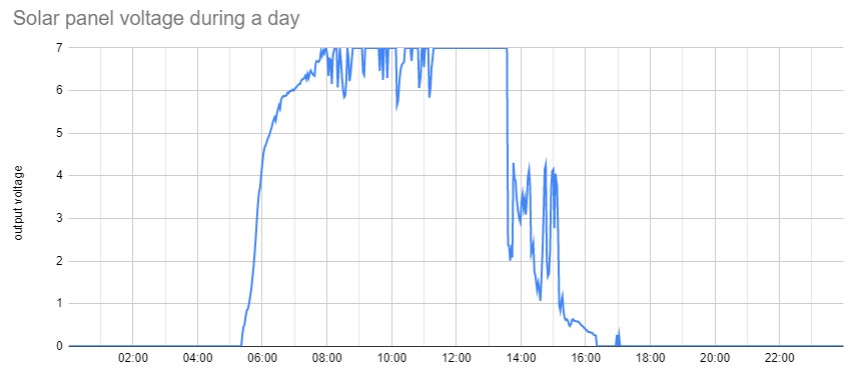
And for the first day in Phy My Hung (May 17th, 2020) we got this graph:
Power measurements with the WEMOS LoLin32 lite:
- On 40 mA, regardless of LED on pin 22, 148 mW
- WiFi 116 mA fluctuating (DHCP, http request), 430 mW, full cycle < 1 second (0.7 s average)
- Sleep 0.06 mA, 0.22 mW - runtime with 1000 mAh battery: 16666 hours, or 694 days
Power measurements with LilyGo TTGO T-Koala with WROVER-B and USB-C
- On 35.8 mA, power LED is always on, 133 mW
- WiFi 100 mA (spikes in oscilloscope, DHCP, http request), 370 mW, full cycle < 1 second (0.7 s average)
- Sleep 0.79 mA, 2.9 mW - runtime with 1000 mAh battery: 1265 hours, or 53 days, power LED is ON
Power output of 6V 2W solar panel on 39 Ohm resistor
2020/05/18
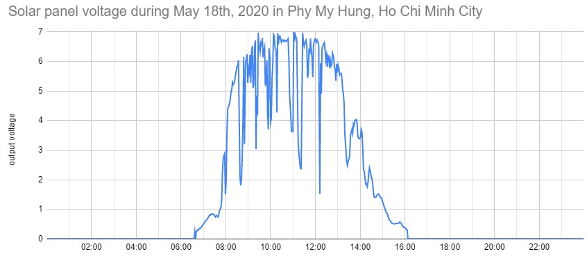
Here is the graph:
2020/05/19
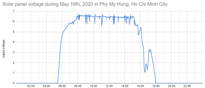
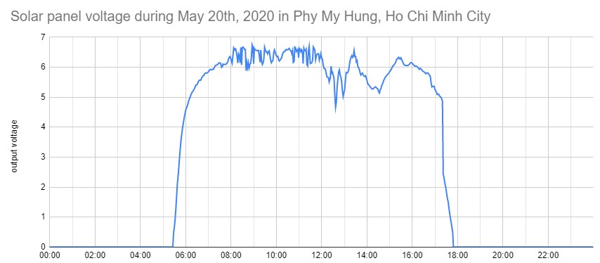
With a load of 3 kOhm we get almost the free floating voltage of the solar cell. At 7 Volt the test circuit only consumes 2.3 mA or 16 mW - while having a maximum power of 2000 mW - this is 0.8% of what it should be able to deliver. Thats the output over the day:
2020/05/21
We installed the second ESP32 next to our MPPT Solar controller and measure for the beginning the voltage of the solar panel and the battery. Observations: The MPPT does not apply for the solar panel, it is directly connected to the battery and looses therefore a lot of energy. Secondly: The floating limit for our battery was set too low at 13.8 Volt, so it was never really charged since installation on May 15th. New limit is 14.7 Volt floating and overvoltage limit 14.8 Volt. Third - the lower voltage limit was set too low at 10.8 Volt, it is adjusted now at 11.0 Volt. The load was reduced from 120 W to 60 W. Let’s see if the weekend brings an improvement. Here is the data from the first day (second half of May 21st, 2020):

Peak voltage and power output of 6 Volt 2 Watt solar panel
2020/05/25
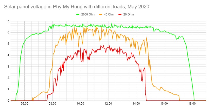
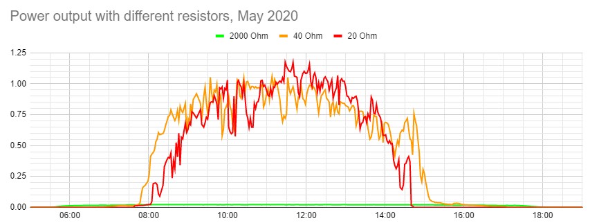
I combined several measurements from May 18th to May 24th with different loads on the 6 Volt 2 Watt solar panel that was placed in Phu My Hung to an overview from 5:00 AM tp 7:00 PM:
Results from first week at AISVN
2020/05/28
We start with a 60 Watt drain resistor that switches on after sunset (6:00 PM) for a programmed time of 4 hours. Unfortunately it drains the battery in 3.5 hours.


Rainy Saturday, battery charged very little, drained after 1.5 hours.


Switch from a 60 Watt load to a 5 Watt load for 4 hours after sunset.

Battery fully charged, controller disconnects solar panel during the day. Load now on for 7 hours after sunset.

Battery drained again with 60 Watt load from 11:00 AM to 5:00 PM. Then installed new MPPT solar charger.

With MPPT higher solar voltage for charging - for increased efficiency. Compare May 28th to May 25th.


Graduation for Seniors 2020 started 3:00 PM after the thunderstorm 1:00 PM - solar panel went off.


Measure the power - resistor for current in line
2020/06/01
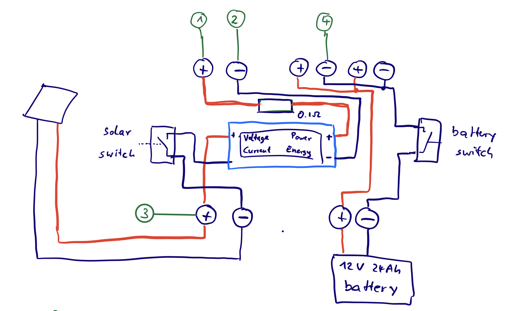
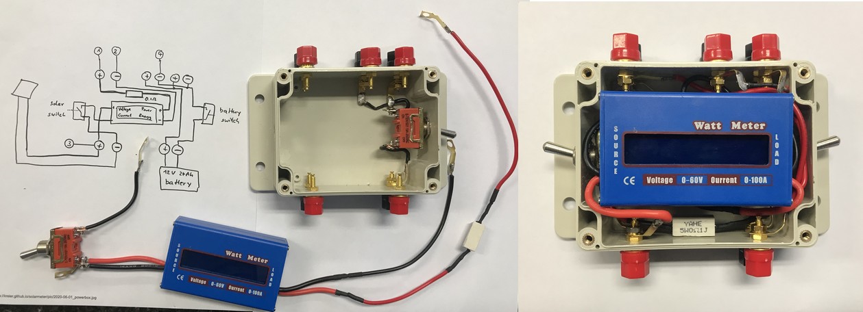
We put a 0.1 Ohm resistor in series with the positive wire of the solar panel to determine the current from the voltage drop. Even in the case of 3 Ampere this accounts only to 0.3 Volt and less than a Watt of heat loss.
2020/06/02
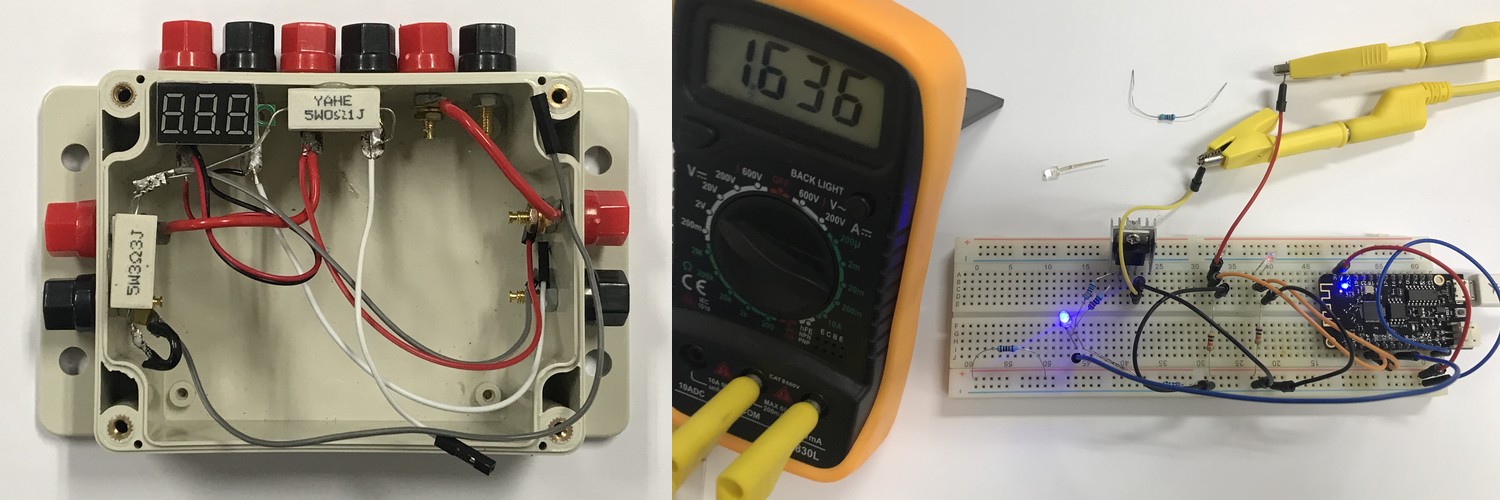
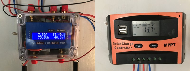
The powerbox was finished. The total resistance is closer to 0.122 Ohm. The voltage drop reading has therefore to be multiplied by 8.2 to get the current reading for the solar panel input. That’s the finished box:
2020/06/05
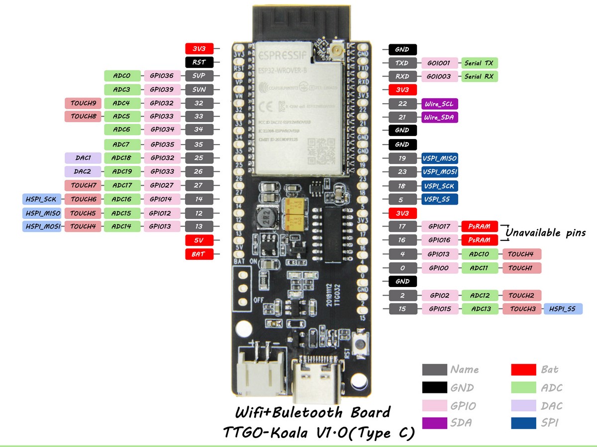
The T-Koala has some direct pins, for example for the battery - it’s easier to connect to them to determine the voltage of the LiPo. Picture and pinout:
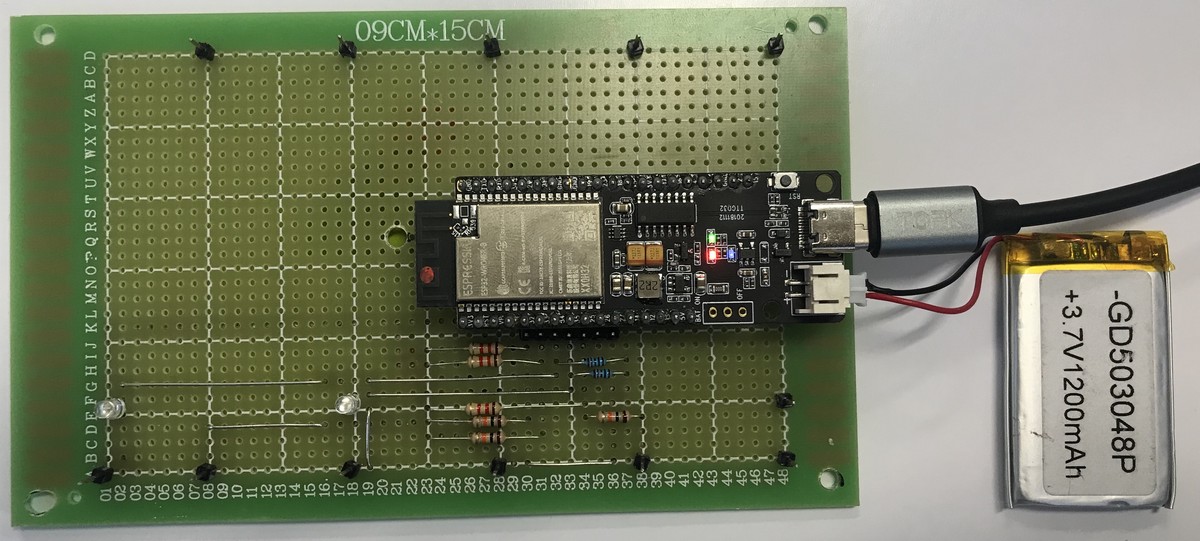
And I finished the soldering of the board with several voltage dividers and two LEDs to lower the voltage into the measurable range of the ESP32 to see the voltage difference over the 0.1 Ohm resistor in line with the solar panel.
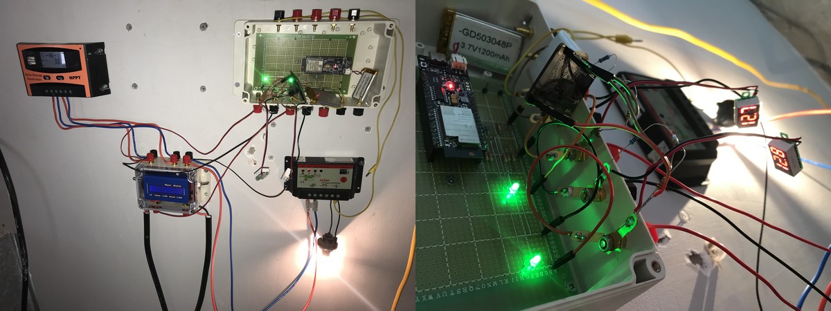
And I installed it after sunset to get the first measurements. It’s installed parallel to the other ESP32 that operated just with 2 voltage dividers for the last 2 weeks - which will cause weired values because of wrong reference levels - and pin26 of the ESP.
2020/06/08
After a weekend of measurement the system is working and delivered the first measured current data - and some strange voltage behaviour once the load switched on.

The power box and MPPT controller measured and displayed their data effectively.
And the final stage for the wind generator and the output measurement was in place:
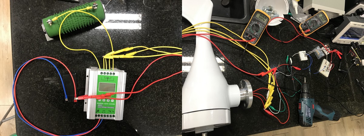
2020/06/09
The mainboard with the TTGO T-Koala ESP32 microcomputer got the rectifying circuit for the 3 phase AC from the wind generator on top. The 6 1N4007 diodes are accompanied by a 100 µF capacitor and a 10 kOhm load to smooth some of the voltage. An blue LED with 10 kOhm is parallel as well. And below is the voltage divider with 1k : 10k as input voltage to pin 26.
In the middle the 100k : 100k voltage divider between GND and battery voltage can be seen as input for pin 13.
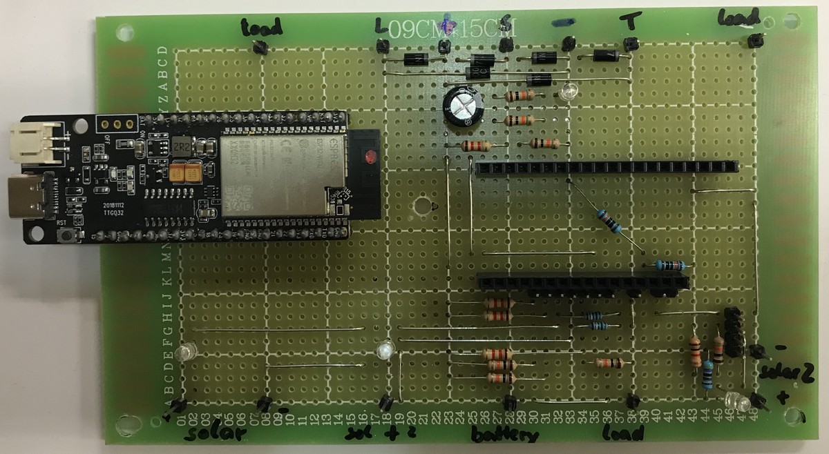
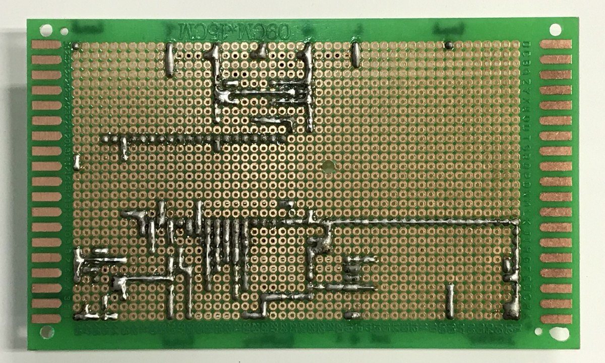
Bottom left are two green diodes that lower the positive voltage of the solar panel prior and after the 0.12 Ohm shunt in line with the positive line. Since positive is connected to 3.3V, the input voltage is 1.1 Volt or higher, if the solar panel provides current. Voltages are measured at pin 34 and 35 and are connected to the negative battery pin with 10 kOhm resistors (the two blue ones) for some 1.2 mA current.
Above the battery pin are the three voltage dividers 1 k : 10 K for solar panel (pin 32), the battery (33) and the load (14). Since all are connected on the positive pin, the voltage is measured against 3.3V and connected to the negative pin with the 10 kOhm resistor.
On the right corner is the small circuit for the second solar cell to charge the LiPo battery of the ESP32. It got its own 4.7k : 1k voltage divider connected to pin 12 and has a step down converter with USB output and a USB-C cable to the connector. The 5V pin of the board can’t be used.
Shortly after 2:00 PM we installed the board, connected the wires and wind generator - and got our first measurement! The rainstorm from 4:00 PM to 5:00 PM provided some constant energy creation.
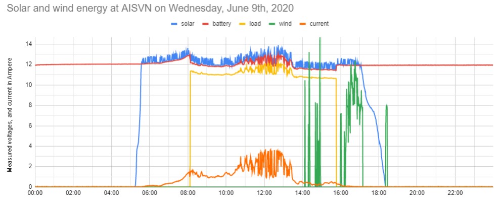
You can see the less noisy signal due to 100x multisampling. As soon as the 20W load lamp switches on the voltage of the battery drops, bust for some time the solar panel can provide the 1.6 Ampere needed, so the voltage stays constant. The clouds at 2:00 PM already indicated the coming storm - and the solar panel virtually started to produce any usable energy. Sunset is indicated at 6:20 PM.
2020/06/11
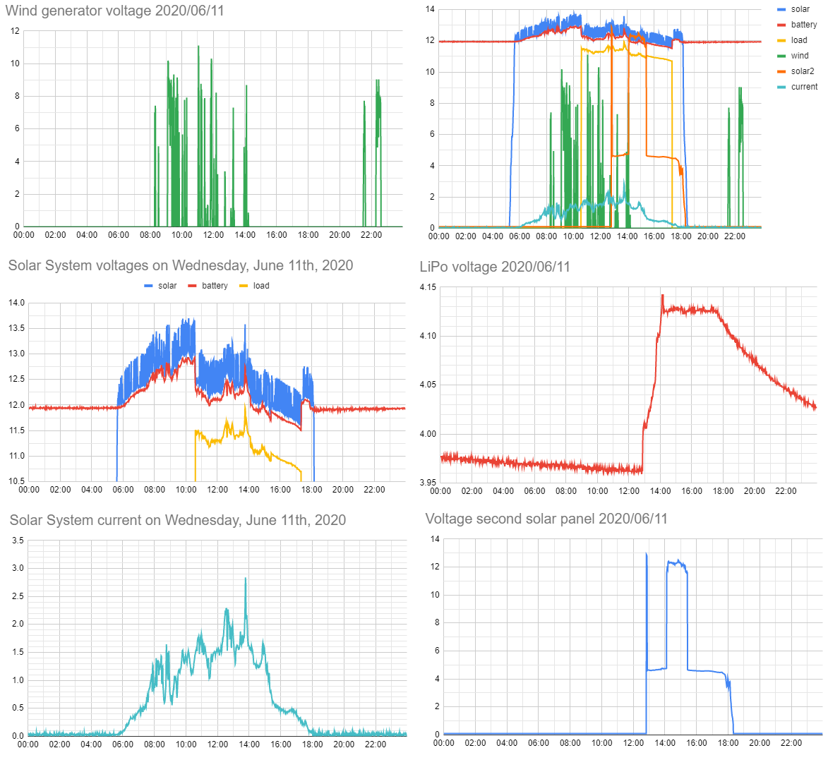
The LiPo battery of the T-Koala would be drained within 2 weeks - on a project with renewable energy! Unfortunately we can’t connect the microcontroller to the big 24 Ah battery, because the solar controller has no common ground, but the positive poles connected. Relative to the negative pole of the battery we get therefore either the full battery voltage during the night or negative voltages (-8 Volt) during the day. Not easy to fit into the 0-3.3 Volt range of the ESP32. Therefore we added a second small solar panel and measure this voltage as well. Here is a collection of our data:

So far we measure the voltages:
- solar panel
- wind generator
- 12V battery
- load
- secondary solar panel
- LiPo battery to power the ESP32
The dump resistor is not yet connected. Additionally we measure the current from the solar panel.
Pin assignment:
//    32,      33,       34,       35,   14,   26,   27,     12,   13
// solar, battery, currentA, currentB, load, wind, dump, solar2, LiPo

int voltage[9] = {0, 0, 0, 0, 0, 0, 0, 0, 0};         // all voltages in millivolt
int pins[9] = {32, 33, 34, 35, 14, 26, 27, 12, 13};   // solar, battery, curA, curB, load, wind, dump, solar2, LiPo
2020/06/12
I combined the mentioned solar panel from yesterday (1 Watt) with a third solar panel to support the hybrid wind station, since the wind generator only seldomly actually charges the battery, the voltage is usually too low. And the small solar panel needs until 9:00 PM to have the LiPo battery recharged from one night of measurement.
2020/06/16
The effect of 100x multi-sampling can easily be seen in this voltage measurement of the LiPo battery for the ESP32. Just compare before (20 mV noise) and after (2 mV noise). Since one measurement is 9.5 µs the 100x multisample takes only a millisecond.

2020/06/18
The second box passed the prove of concept: I’m able to switch up to 1.5 Ampere with a 2SD613 transistor and a 150 Ohm resistor connected to an output of the ESP32. And the output stays active even in deep sleep with the right software. And the measured data make sense, a draft software script is uploaded as SolarAISVN2.ino in the software folder. Most of the box inner is ready as well, only the PCB needs to be finished:
