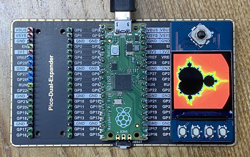
rp2040


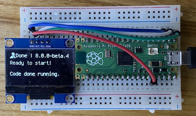
Example programs in CircuitPython and C for the Raspberry Pico 2040. We use it with 3 different external displays as more detailed optical output than just the led.
320x240 ili9341 3.2 inch tft
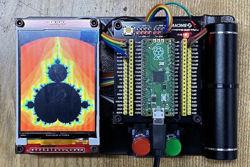
3.2 inch display at thegioiic.com
240x240 st7789 1.3 inch waveshare tft
1.3 tft display documentation at waveshare
| TFT | Pico | Description |
|---|---|---|
| VCC | VSYS | Power Input |
| GND | GND | GND |
| DIN | GP11 | MOSI pin of SPI, slave device data input |
| CLK | GP10 | SCK pin of SPI, clock pin |
| CS | GP9 | Chip selection of SPI, low active |
| DC | GP8 | Data/Command control pin (High for data; Low for command) |
| RST | GP12 | Reset pin, low active |
| BL | GP13 | Backlight control |
| A | GP15 | User button A —– left button |
| B | GP17 | User button B —– right button |
| X | GP19 | User button X |
| Y | GP21 | User buttonY |
| UP | GP2 | Joystick-up |
| DOWN | GP18 | Joystick-down |
| LEFT | GP16 | Joystick-left |
| RIGHT | GP20 | Joystick-right |
| CTRL | GP3 | Joystick-center |
| SDA | GP0 | i2c data line for OLED and external sensors |
| SCL | GP1 | i2c clock for OLED and external sensors |
128x64 sh1106 1.3 inch oled
1.3 inch oled at thegioiic.com
128x32 ssd1306 oled adafruit
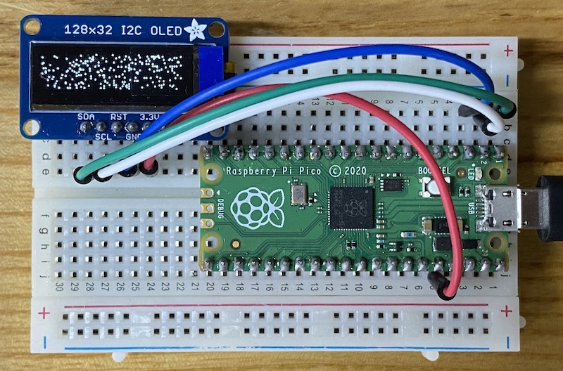
Adafruit documentation circuitpython
rp2040 and i2c sensors
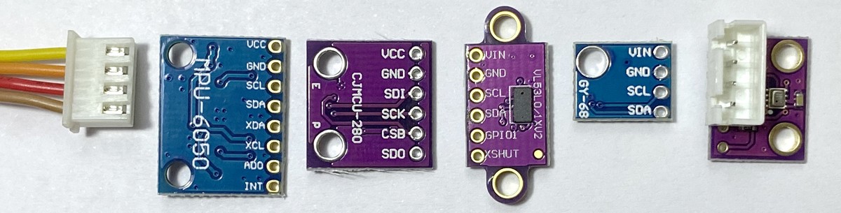
We would like to just solder a 4-pin JST XH 2.54 mm pitch (0.1 “) connector to any of these boards and then use a standard XH-4 cable to connect to our ssis:bit without worrying about polarity or correct pin order:
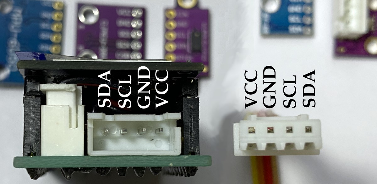
The order of pins in the 1mm QUIIC connector is different from the order of the 4 pins found in virtually every hobby board with 2.54mm pins:
Hopefully we soon have a little shelf with all these different sensors for ‘plug and play’ and a software library on our boards.