After School Activity #3 2019-2020
This third ASA session was planned in December 2019 to build an explorer robot with 4DOF arm, running MicroPython, created at AISVN.
Due to COVID-19 this session never started. This repository was created in December 2019 as preparation for the upcoming season. It’s here for documentation purposes. Below a few steps of planning:
Pictures from our T400 build at ASA session 3
Session 3 is from February 24th to May 29th. We have these 11 sessions:
- February 25th
- March 10th
- March 17th
- March 24th
- April 7th
- April 14th
- April 21st
- April 28th
- May 5th
- May 12th
- May 26th
Some pictures of our progress:
ESP8266 with Micropython - Text and graphics on 128x64 OLED i2c display
We use pin D5 (GPIO14) as SDA and D6 (GPIO12) as SCL for the i2c bus. The driver library 1306.py should be installed on the device. You can show any image 128x64 monochrome image. For example:


The code used is splash3.py.
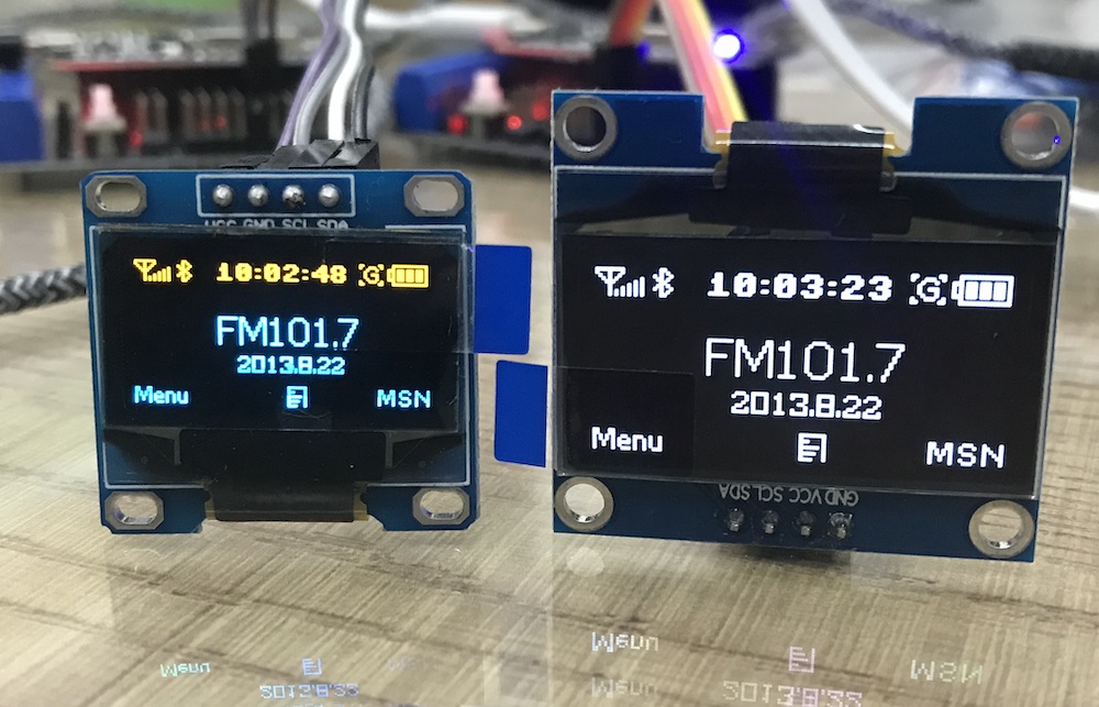
Size 0.96 inch or 1.3 inch
For comparison I ordered the slightly larger display with 1.3 inch as well. It needs the different sh1106 driver, but has the same functions as the ssd1306. Text is easier to read. Here an image:
Convert images
I use the online tool from majer.ch and convert the code from ‘, 0x87’ to ‘\x87’ in the bytearray. Follow this instructions:
To create an image there is a description at the micropython forum. In short deshipu says:
The buffer in the previous exampe is created by scanning the original image pixel-by-pixel and setting the bits of the bytes depending on whether they are supposed to be on or off. The alignment of the bytes is as follows (example of a 16x16 image, the digits signify the bits of each byte):
a7 b7 c7 d7 e7 f7 g7 h7 i7 j7 k7 l7 m7 n7 o7 p7
a6 b6 c6 d6 e6 f6 g6 h6 i6 j6 k6 l6 m6 n6 o6 p6
a5 b5 c5 d5 e5 f5 g5 h5 i5 j5 k5 l5 m5 n5 o5 p5
a4 b4 c4 d4 e4 f4 g4 h4 i4 j4 k4 l4 m4 n4 o4 p4
a3 b3 c3 d3 e3 f3 g3 h3 i3 j3 k3 l3 m3 n3 o3 p3
a2 b2 c2 d2 e2 f2 g2 h2 i2 j2 k2 l2 m2 n2 o2 p2
a1 b1 c1 d1 e1 f1 g1 h1 i1 j1 k1 l1 m1 n1 o1 p1
a0 b0 c0 d0 e0 f0 g0 h0 i0 j0 k0 l0 m0 n0 o0 p0
q7 r7 s7 t7 u7 v7 w7 x7 y7 z7 A7 B7 C7 D7 E7 F7
q6 r6 s6 t6 u6 v6 w6 x6 y6 z6 A6 B6 C6 D6 E6 F6
q5 r5 s5 t5 u5 v5 w5 x5 y5 z5 A5 B5 C5 D5 E5 F5
q4 r4 s4 t4 u4 v4 w4 x4 y4 z4 A4 B4 C4 D4 E4 F4
q3 r3 s3 t3 u3 v3 w3 x3 y3 z3 A3 B3 C3 D3 E3 F3
q2 r2 s2 t2 u2 v2 w2 x2 y2 z2 A2 B2 C2 D2 E2 F2
q1 r1 s1 t1 u1 v1 w1 x1 y1 z1 A1 B1 C1 D1 E1 F1
q0 r0 s0 t0 u0 v0 w0 x0 y0 z0 A0 B0 C0 D0 E0 F0
I used the following code to generate it:
import pygame

image = pygame.image.load("1bit-logo.png")
buffer = bytearray((image.get_height() // 8) * image.get_width())
i = 0
for y in range(image.get_height() // 8):
    for x in range(image.get_width()):
        byte = 0
        for bit in range(8):
            pixel = image.get_at((x, y * 8 + bit))
            if pixel[0] != 255:
                byte |= (1 << bit)
        buffer[i] = byte
        i += 1
print(repr(buffer))
After that kamikaze added: or you could use ImageMagick's convert and store it in file to save RAM
Robot base
This part is documented at aisvn
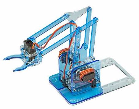
Robot arm - MeArm v1.0
Since the flawed version v0.4 from April 2014 is still sold at lazada.vn and aliexpress.com we look forward to create the much improved v1.0 from MeArm (or phenoptix alias Ben Gray from Nottingham) or Mime Industries. It was published September 2015. Thanks to a successful Kickstarter campain from 2014.
Instructions for assembly
- At learn.mearm.com
- Instructables v1.1
- As pdf from mearm v1.4 from 2015
- PDF export of v1.1 from 2016
Lasercut files
The files can be found at:
- Thingiverse 993759 from September 2015
- Old v0.4 from April 2014
- Updated v1.1 on GitHub from March 2017
- Updated v3.0 from February 2019 - needs M2.5 screws!
Additional materials
v1.0
You will need some screws and nuts M3 as well. Specifically:
- 10x - M3 Nut
- 6x - M3 x 6mm
- 15x - M3 x 8mm
- 3x - M3 x 10mm
- 8x - M3 x 12mm
- 4x - M3 x 20mm
Old materials for v0.4
- M3 Nut x 10
- 6mm x 9
- 8mm x 12
- 10mm x 3
- 12mm x 7
- 20mm x 4
MeArm v3.0
In new version v3.0 from the renamed company Mime industries.
To assemble you can follow the instructions in the pdf or watch the following video:

The lasercut files can be found on thingiverse 3420797. But it needs M2.5 screws. I guess it is:
- 10x - M3 Nut
- 6x - M2.5 x 6mm
- 15x - M2.5 x 8mm
- 3x - M2.5 x 10mm
- 8x - M2.5 x 12mm
- 4x - M2.5 x 20mm
And we need a pcb at the bottom.